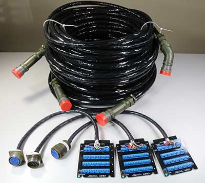
1 - These three test interface fixtures for circular connectors comprise CB29 series connector boards and flying leads. Built for a shipyard application, the UUT is shown in the background.
Application: Shipyard
![]() +1 978 266 2655
+1 978 266 2655
2 - Customer, Entertainment Manufacturing Group, embeds CableEye HVX systems within their mobile test laboratories.
Photo Credit: EMG
Application: Entertainment/Events
3 - Our distributor, Incore Technology (Korea), designs and manufactures custom interfaces such as these test interface panels.
Photo Credit: Incore Technology
4 - Custom test interface fixtures (with UUT) designed to attach to control module of a CableEye tester via CB48B Header Isolator ™ adapters.
Application: Home Appliances
5 - Custom test interface fixture designed to attach to control module of a CableEye tester via CB48B Header Isolator ™ adapter.
6 - Customer, Becker GmbH, embeds CableEye LV systems within their mobile test benches.
Photo Credit: Becker
Application: Robotics
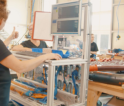
7 - Customer, EV Cables Wottz, built panels to test EV charging cables with their CableEye HVX system.
Photo Credit: EV Cables Wottz
Application: Electric Vehicles
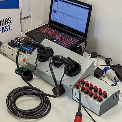
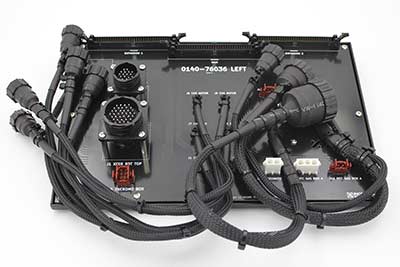
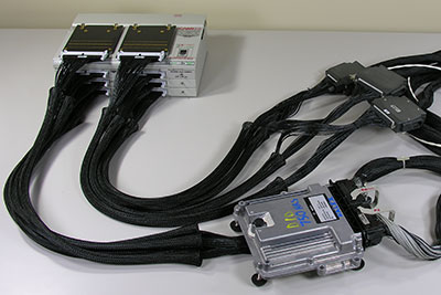
7 - We specified a custom-machined Delrin block to support the long gray and black connectors on the left side of this fixture. These unusual connectors were designed to be embedded in PLA control housings and would not have withstood the continuous testing that the customer required for their cables without this extra support. The right side of their test cables have either standard dual-row sockets, or bare wires, necessitating the pushpin blocks you see on the right.
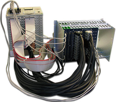
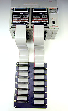
8 - We built this interface for a customer who needed to test a complex multi-headed telecom cable consisting of fourteen 64-pin Centronics-style connectors. This CableEye unit has seven expansion modules to provide 896 test points.
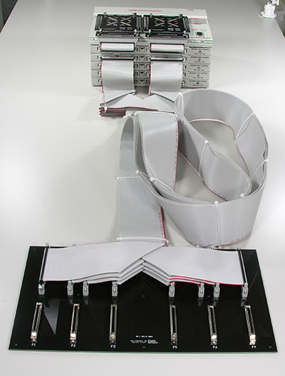
9 - A harness assembly board (top piece) is placed over a mating harness board prior to testing. Click this image, or here, for additional explanation about wire harness testing.
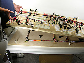
10 - This complex wire harness interconnects flight instruments in the cockpit of a small aircraft. Click this image, or here, to see the custom harness interface we built to test it.
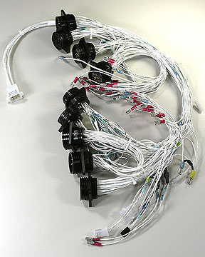
Photo Credit: Anonymous Customer
Application: Defense/Aerospace
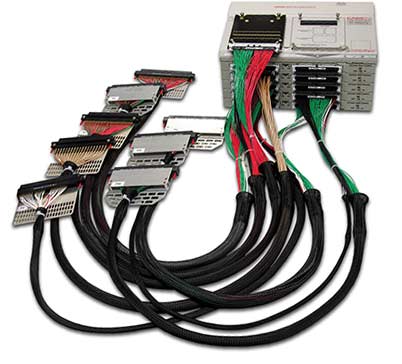
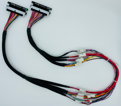
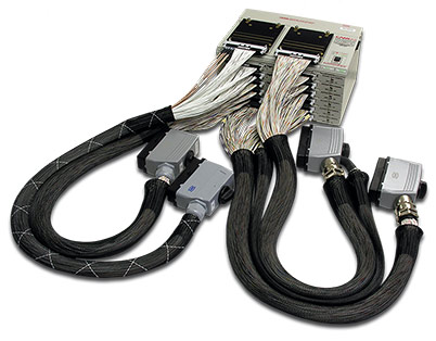
12 - These adapter cables which have Virginia Panel ZIF connectors as the mating part, connect directly to the CableEye tester, each using multiple 64-pin AMPMODU connectors. No CB boards are involved. This is a perfect example of test cables with connectors too large to mount directly on a board.
Although we show an 896-point low voltage tester here, these AMPMODU adapter cables could also be directly connected to a CableEye HVX-Series High Voltage Test System and run at test voltages of up to 2100Vdc.
Application: Defense/Aerospace
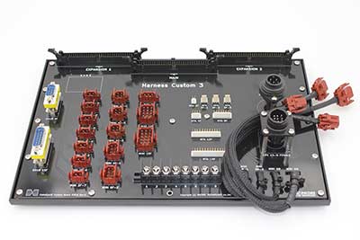
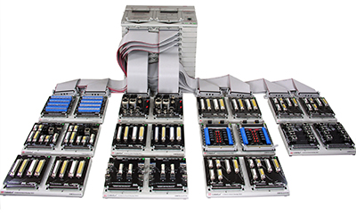
13 - With the help of eleven QuickMount™ housings (catalog Item 712), this 1536 test point low voltage test system can mount up to 24 CB boards simultaneously, two on the control module and 22 on the QuickMount housings.
When using standard CableEye CB plug-in boards (or CB boards of your own design), the boards may be mixed and matched in any order with this truly plug-and-play system to instantly obtain the connector interface you need. Note that if you learn a cable with the boards in one arrangement, and later test an identical cable with the boards plugged into different locations, the CableEye software figures this out automatically, so you need not pay attention to the exact locations where boards are connected.
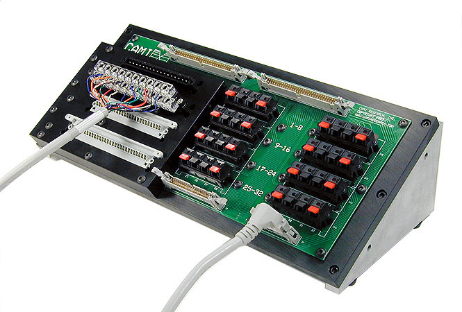
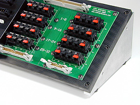
14 - We designed the black board you see in the front of this photo as a custom-transition board that adapts six 68-pin connectors to eight 64-pin headers that attach to a customer's 768-point low voltage CableEye tester using standard 64-conductor flat cable. Test points on the control module and first expansion module are not used in this application.
Flat cables* have the advantages of being inexpensive to build and easily folded to adapt to situations like this.
*Use AMPMODU discrete wire cables for test voltages above 500V.
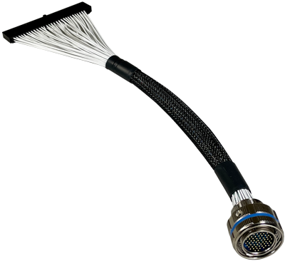
15 - You can see only part of the customer's test cable in the right side of this photo. The interesting point about this application is that one side of the test cable is attached to a special piece of equipment for which no mating connector was available. We were given an aluminum housing with a circuit board and its built-in mating connector to work with, so we cut away the circuit wiring while leaving the PC board in place, and replaced these circuit connections with wires from our adapter cable. We attached special rubber feet to this housing which would otherwise have bolted to the firewall of a vehicle.
Application: Automotive
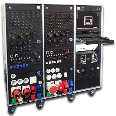
16 - This 1920 test point system is configured for back panel testing with flat and AMPMODU mating adapters.