Category Index
Adapting to Connectors on your Cables
Electrical Measurements on a Cable
Connector Graphics
Computer Requirements and Options
Data Export/Import
Choosing the Right CableEye Model
Learning to Use CableEye Test Equipment
Product Support Subscription
Calibration
PC-Based Systems
Adapting to Connectors on Your Cables
Adapting to Connectors on Your Cables
Next | Previous | TOC
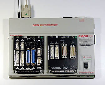
Can different types connector boards be used at the same time (for example CB15 on the left and CB4 on the right), or must you use like boards on each side of the tester?
You may mix and match boards in whatever combination you require to test the cable. Each CB board as an ID jumper built into the board that identifies it to the software allowing the proper choice of a connector graphic.
Adapting to Connectors on Your Cables
Next | Previous | TOCThe connector boards generally have two or more connectors mounted on a single board. Can I use more than one at a time when checking multi-headed cables?
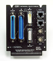
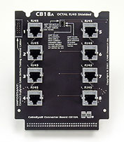
Generally you may use only one connector at a time on each board. The connectors usually share a certain number of test points on each board, and it is the shared test points that cannot be employed simultaneously. There are exceptions, though. For example, the CB1 board you see on the right has two BNC connector that were layed out on the board to have independent test points, and thus these two connectors may be used at the same time. In this case, you would mount a CB1 on each side on the tester and would have a total of four BNC connectors available for your multi-headed cable. A similar situation exists for the CB18A board which has eight independent RJ45 connectors.
To test multi-headed cables, you may mount three or more boards by using an expansion module (low voltage series, high voltage series), use adapter cables, or build a panel connected directly to the CableEye tester and having all the connectors you need pre-mounted (click for examples).
Adapting to Connectors on Your Cables
Next | Previous | TOCHow do I interface unusual connectors to the tester?
One approach would be to use our universal CB8/H, CB30/H, or CB60 boards. Three different connectors are mounted on the CB8 board you see on the right. The connectors may be removed and the board reused for another application. We are pleased to design and build custom interfaces for you at very reasonable rates. Contact us for details. See more examples of customized CB8 boards.
.jpeg)
Adapting to Connectors on Your Cables
Next | Previous | TOCIs it possible to design and build our own CB interface board?
Yes. We will happily provide you with the routing pattern for the board as shown on the right (the data we give you will have exact dimensions). We can provide suggestions too for laying out the board and positioning the connectors.
Adapting to Connectors on Your Cables
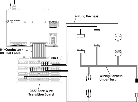
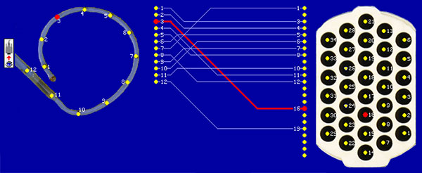
Next | Previous | TOCHow do I set up my CableEye tester for wire harness testing?
Depending on the size of the harness, you may (a) build a mating harness as shown on the right, (b) construct a panel with all of your connectors present, (c) build "pigtail" cables, or (d) mount mating connectors on CB8 or CB30 custom interface boards. Our PinMap™ fixture editor software (Item 708) lets you add custom labels to all of your connectors and pins. We are pleased to advise during the construction of your harness interface.
Electrical Measurements on a Cable
Electrical Measurements on a Cable
Next | Previous | TOC
Does one connector board serve as a signal driver and the other as a receiver?
No. Although this kind of design is used in some very inexpensive cable testers, it does not provide a comprehensive test. In CableEye testers, every test point serves as both an input and an output at different times during the measurement of a cable. This permits us to measure current in both directions, and thus detect diodes. Every test point is measured with respect to every other one. So, for the 128 test point address space of a CableEye M2Z tester, 128*128 (=16,384) measurements are made. The fact that we divide the 128 point space between two 64-pin headers is a matter of physical design only. It could just as well have been divided between four 32-pin headers.
Electrical Measurements on a Cable
Next | Previous | TOCCan a CableEye tester measure a jumper between two pins of the same connector?
Yes. Any physically possible network of wiring may be measured and stored in the database as a reference for future testing.
Electrical Measurements on a Cable
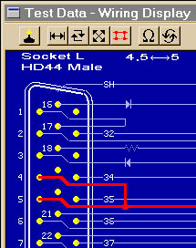
Next | Previous | TOCWhat is a "resistance threshold" and how does it affect testing a cable?
With the exception of the M2 series, all CableEye test systems permit you to set two resistance thresholds, a "conduction" threshold and an "isolation" threshold as specified in the Technical Specifications. These user-set values become test Pass/Fail criteria, and allow you to check the quality of your connections.
The "conduction" threshold is the highest resistance value you allow for a good (Pass) connection. Typically, in LV applications, you would set the value to about 2 Ω, in which case any wire whose resistance is less than 2 Ω is consider a "good" connection. For long cables, this value would increase to allow for the natural resistance of wire (typically 0.1 Ω/ft). If this threshold is violated during a test, the cable will be flagged as faulty (Fail).
The "isolation" threshold is the lowest value of resistance you allow for wires in a cable that are not connected. Typically, in LV applications, you would set this value to 1 MΩ or higher (Pass). When wires that are not suppose to be connected show leakage resistance less than this threshold, say 100 KΩ rather than 1 MΩ, the cable will be flagged as faulty (Fail). Isolation failures rarely occur with the cable body itself, but are more likely found within a connector as a result of solder or crimp terminations being too close, or contamination being present (such as solder flux or sugar residue from a beverage).
In short, to check the QUALITY of a connection, a cable must be checked against both of these thresholds which the test manager must set at levels that are appropriate for the application. A cable that passes the basic continuity test might fail the quality of connection test.
The diagram to the right illustrates typical LV applications.

Electrical Measurements on a Cable
Next | Previous | TOCWhat are the benefits of setting resistance thresholds?
Improper crimps, partially broken conductors, corrosion, and wear are some conditions that will cause high resistance on a pin when the cable is attached. Setting a threshold for maximum allowable resistance (generally 2-10 Ω for LV applications) flags any suspect connections. In addition to testing for good connections, with the exception of the M2 series, all CableEye systems permit you to set an isolation threshold (see Technical Specifications) to ensure that insulation is not compromised. Contamination between pins by solder flux or moisture could cause an isolation failure. In otherwords, in setting resistance thresholds, you are able to test and check the quality of your connections. A cable that passes the basic continuity test might fail the quality of connection test.
Electrical Measurements on a Cable
Next | Previous | TOCCan you set thresholds on the Model M2 series testers?
The Model M2Z and now obsolete M2U-Basic and M2U testers have a single fixed threshold of 42 KΩ that cannot be changed. This threshold value makes these models very sensitive to short circuits, the most serious and most likely kind of problem within a cable.
Electrical Measurements on a Cable
Next | Previous | TOCWhat voltage is applied to the cable during testing?
This is model-dependent, ranging from a few volts to >1KV as specified in the Technical Specifications.
Electrical Measurements on a Cable
Next | Previous | TOCHow long does it take to measure a typical cable?
All our models are USB certified yielding fast test times. Low voltage tests performed by unexpanded Control Modules are literally faster than the blink of an eye (see Technical Specifications).
Electrical Measurements on a Cable
Next | Previous | TOCWhat is the maximum length of cable I can measure?
That depends on the cable's capacitance and inductance. This is affected by the amount of wire twisting in the cable, and whether a shield conductor surrounds the wires. For unshielded Cat 5 ethernet cable which has twisted pairs, we have successfully measured cables 1000 ft long, though have not tested for maximum length. For 25-pair Telco shielded Telco cable, we have customers who regularly test cables of several hundred feet long. Again, they have not tested for maximum length. Another customer successfully tested simultaneous, multipoint continuity in a two-mile long, multicore cable (rated at 10Ω/1000ft) using a CableEye M3UH tester. Neither is this a maximum length. All our testers have a "dwell time" adjustment that affects how long a test signal is applied to a conductor during measurement. The dwell time may be increased as necessary to permit measuring extremely long cables.
Electrical Measurements on a Cable
Next | Previous | TOCAre "test points" the same as wire connections?
No. For each wire, you need two test points, one on one side of the wire and one on the other. To test a 40 conductor cable, you need 80 test points. Add two more test points if there is a shield. Double the number of required test points if you are employing precision 4-wire resistance measurement methods.
Example: CableEye tester Control Modules with 152 test points can check a cable as large as 76 conductors when using standard 2-Wire measurement techniques, and a cable as large as 38 conductors when using 4-Wire measurement techniques. (4-Wire measurement is available for the M4- and HVX-series testers.)
Electrical Measurements on a Cable
Next | Previous | TOCHow many test points do I need for my application?
Simply add the total number of pins on all connectors of your largest cable. Be sure to include the shields. For example, if you had a two-ended cable with DB25 connectors at each end, you need 26 test points for each end (25 pins plus a shield), and thus a total of 52 test points would be needed. For a wire harness having ten connectors of 30 pins each, you would need 300 test points. For the same harness, if you need to employ precision 4-wire measurement techniques on every pin, you will need 600 test points (double the test points).
Technical Specifications: CableEye test system Control Modules have 128 test points or 128 test points + 24 accessory test points depending on the model. The maximum number of test points is also model-dependent, and may exceed 2500 through use of expansion modules. 4-Wire measurement is available for the M4- and HVX-series testers.
Electrical Measurements on a Cable
Next | Previous | TOCCan Models M3Z, M4, HVX, and HVX21 measure resistor values?
Yes. In addition to checking cable conductors against resistance thresholds to verify the quality of your connections, embedded resistors may be checked to levels specified in the Technical Specifications.
Electrical Measurements on a Cable
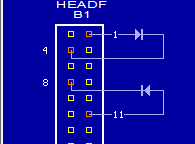
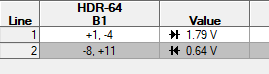
Next | Previous | TOCCan CableEye testers measure diode values?
Yes. All models check forward voltage. In addition, with the exception of the M2 series, they also check reverse voltage and polarity. See Technical Specifications.
Electrical Measurements on a Cable
Next | Previous | TOCCan CableEye testers measure capacitance and capacitor values?
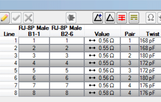
Yes. Models M4 and HVX series fitted with Advanced Measurements option will measure polarized and unpolarized capacitors, capacitance between wires, distance to break, length of cable, and twist pairing. See Technical Specifications.
Electrical Measurements on a Cable
Next | Previous | TOCCan CableEye testers test an IC?
No. You need an ATE circuit tester for that (MUCH more expensive). However, we do have customers that have single-ended cables that terminate in an unpowered semiconductor circuit containing capacitors and resistors in addition to ICs. Semiconductors and capacitors will create diodes and bogus resistors in the test report. What we can do in that case, with judicious adjustment of the dwell time and high threshold in an HVX series tester, is obtain a “signature” (that is, a repeatable series of resistors, diodes, and wires without specific meaning) to determine if the cable connected to the circuit has any opens or shorts present. If the signature changes, this flags a failed cable, or a failed or missing component on the circuit, but may not tell you exactly why.
Electrical Measurements on a Cable
Next | Previous | TOCHow do I determine which connector boards I need?
Have a look at our Connector Board Selector as a guide in choosing your boards.
Connector Graphics
Connector Graphics
Next | Previous | TOC
With two or more connectors on a single plug-in board, how does the CableEye test system know which connector to use for the graphic wiring display?
Although we mount several connectors on each board, we designed the board so that at least one test point is uniquely assigned to each connector (typically the shell conductor). Thus, when a CableEye tester detects a signal on this unique test point, we know which connector is being used.
Connector Graphics
Next | Previous | TOCCan I create my own connector graphics for our CableEye tester?
Yes! We offer optional Connector Designer™ connector editor software (Item 707).
Connector Graphics
Next | Previous | TOCIf I mount my own connector on the CB8/CB30/CB60 prototyping boards, or via an interface cable, what graphic does the CableEye test system use and how can I change it?
Because the CB8/H, CB30/H, and CB60 boards are generic (i.e. designed for any connector type), the software defaults to a 64-pin dual-row header as seen on the right. The pin numbers match the pad numbers on the board, and the wiring will be shown accurately, but the geometric shape of the connector will be rectangular. With the optional PinMap™ fixture editor software (Item 708), you may replace the rectangular header graphic with anything else in the library. You may also add images of your unique connector developed with the optional Connector Designer™ connector editor software.
Connector Graphics
Next | Previous | TOCCan I change the pin labels on a connector graphic?
Yes. You would use the PinMap™ fixture editor software (Item 708) for this purpose and can have up to a seven character alphanumeric label on each pin. When testing wire harnesses or multi-headed cables, you would typically incorporate the connector name into the pin number. For example, connector J3 pin 28 might have a pin label J3:28.
Computer Requirements and Options
Computer Requirements and Options
Next | Previous | TOC
What kind of computer and operating system do I need to run the CableEye tester software?
Your CableEye system requires a Windows® PC (desktop, laptop, or all-in-one) to run the CableEye software. The tester measures the cable under test and transmits raw measurement data to the PC. The tester cannot be operated without a computer! The computer should meet the following requirements:
- Operating System - Windows 10 or newer.
- Computer Specs - Any computer supporting Windows 10 or above is enough to run the software.
- USB Ports - One port for low voltage testers, two ports for high voltage testers, plus additional for other devices (mouse, keyboard, printer etc).
- Printer - Any standard or label printer, local or on the network.
- Touch Screen - Optional but recommended for production.
We recommend the largest monitor reasonable for your application: Testing large harnesses? Choose a large screen. CableEye testers do not limit your choice. CableEye tester software version B1188 or later is giving you the option of removing other peripherals from your production workstation.
You may use a network printer to print reports. Two or more printers may be used simultaneously. For example, you may wish to have one for printing reports and another for printing labels.
Computer Requirements and Options
Next | Previous | TOCCan I load the CableEye tester software on two or more computers at a time?
Yes, however, the test fixture must be connected to the computer's USB port for the software to operate. You have permission to load the software on as many computers as you wish, and then move the test fixture around as needed to different work stations for testing cables or wire harnesses.
Computer Requirements and Options
Next | Previous | TOCCan I install the CableEye tester software on a network so that two or more workstations can share the same cable database and log files?
Yes. Set up a shared folder with the CableEye tester database contained therein.
Note that, using the standard software license, the software will not actually start unless the tester is attached to the computer and detected during the startup sequence. If you purchase our Standalone Enabler option (Item 729), the software will startup if the tester is not present, permitting other users to view and edit cables, view reports, print labels, and perform any function that does not require data acquisition from the tester.
Computer Requirements and Options
Next | Previous | TOCIs it possible to use the software without the test fixture connected if all I want to do is look at cable schematics, design cables, view reports, or print labels?
If you purchase the optional Software Site License (Item 729), you may do so. In this case, any computer on your network may start the CableEye software and use any of the software functions, including report printing, that do not require the test fixture.
Computer Requirements and Options
Next | Previous | TOCIs is possible to use two or more testers with a single computer as long as one USB port is available for each tester?
Technically, yes, but this is not recommended. Each operator needs their own controls and video display to operate the tester and see results.
Data Export/Import
Choosing the Right CableEye Model
Choosing the Right CableEye Model
Next | Previous | TOC
Which model tester would be best for my application?
You may choose from several CableEye tester models with varying prices. Use our Product Selection Wizard and Specification Sheet to find the best match to your needs.
Choosing the Right CableEye Model
Next | Previous | TOCCould you provide references to people currently using the CableEye tester?
Yes, we will happily do so. Call us at the number shown below and ask for a reference list of customers in your area.
Tel: +1-978-266-2655
We also have many testimonials posted online.
Learning to Use CableEye Test Equipment
Learning to Use CableEye Test Equipment
Next | Previous | TOC
How long will it take to learn how to use a CableEye test system?
Most people have the hardware connected, the software installed, and begin testing within about 10 minutes.
The software is very easy to use and should not pose any problems for unskilled operators.
To set up scripts for automatic production testing, to customize reports, or adapt to custom cables, you would first review the relevant sections in the CableEye Software Introduction Guide, and then perhaps the associated CableEye User's Manual if further detail is required.
Learning to Use CableEye Test Equipment
Next | Previous | TOCHow can I ensure that unskilled operators in a production environment test the cables consistently and cannot tamper with the settings?
CableEye software includes a simple scripting language that lets the test engineer set up the desired test sequence including report generation and label printing, in advance. The operator needs only to press the TEST button on CableEye to trigger a test sequence.
You may also activate the Production Mode with a single click, and set up operator names with passwords and privilage controls to write-protect the database, threshold settings, and scripts.
Product Support Subscription
Product Support Subscription
Next | Previous | TOC
What if I need help with the equipment or software?
The renewable two-year Product Support Subscription provided with each new tester includes free tech support, free software updates and upgrades, a warranty and more. Go to our Customer Support for all your support information.
Product Support Subscription
Next | Previous | TOCIn the event that a repair is needed, what kind of turn-around can I expect?
Repairs on equipment with a Product Support Subscription are given priority. We generally complete simple repairs on basic systems within 24 hours of receiving the equipment. If we receive it early enough, we may be able to ship the unit back the same day. Check here for our current lead times.
Product Support Subscription
Next | Previous | TOC
What are my service options after the first two years?
You may renew the Product Support Subscription at the end of the second year of ownership to maintain your free software upgrades, free tech support, warranty and more.
Calibration
PC-Based Systems
PC-Based Systems
Next | Previous | TOC
Are all test systems marketed as PC-based actually PC-based?
CAMI's products are all PC-based, but not all test systems are: Because PC-based equipment offers many benefits not found in standalone units, there is an incentive for everyone selling test equipment to use the words "PC-Based" and "PC" in their publicity whenever remotely possible. As a result, the meaning of "PC-based" is often lost.
Numerous test instruments permit the upload and download of information to PC software merely for off-line data analysis and storage. As such, these instruments do not qualify as "PC-based".
Microprocessor-controlled systems do not qualify as "PC-based" either. They have a limited user interface, often focused on hardware.
PC-Based Systems
(end) | Previous | TOCWhy use a PC-Based test system?
Read more.
- The electronic hardware specific to the tester consists of a data acquisition unit only, resulting in simpler, less-expensive hardware than testers that contain an embedded PC with disk drive, display subsystem, and microprocessor support circuitry.
- Customers may use existing PC hardware that may already be available at no cost to their company.
- Because the tester links to the PC via the USB port, no internal plug-in board is required. Thus, should the PC fail, the tester and software can quickly be moved to another PC for uninterrupted operation.
- With the software designed around a fully-functioning PC (monitor, hard disk, etc.) more advanced software becomes possible than if the design were centered around a small, onboard, display.
- Customers may use a readily-available laptop PC for field use where the laptop manufacturer has already invested considerable R&D in miniaturization and ruggedness. Thus, the total package of laptop PC and data acquisition unit becomes much more suitable for portable use than a unit with an integrated PC controller.
- Customers receive software upgrades that add significant new capabilities with no changes in hardware, minimal cost, and no ship-back of equipment.