Easily Link to Custom Cable Harness Fixtures
Summary
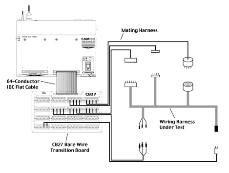
- Connect directly to your CableEye® tester with 64-conductor flat cable, no connector boards required.
- Use our CB27 Bare Wire Transition Board for easy connection to the mating harness.
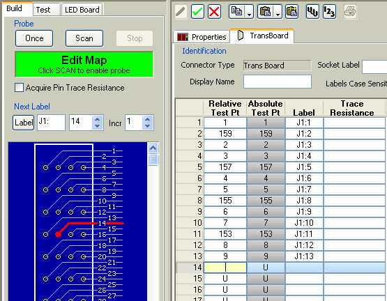
- Map your mating harness or custom connector panel instantly using our PinMap™ fixture editor software and probe.
- Create custom pin labels with the PinMap fixture editor software (see screen image below).
An Example
In the drawing below, we use the CB27 Bare Wire Transition Board (Item 757) to interface the mating harness to the CableEye tester. When the mating harness consists of discrete wires, using CB27 provides an easy interface. If you can terminate the mating harness in 64-pin IDC socket connectors, you may plug those connectors directly into the latch headers on the tester. Another approach would be to terminate the mating harness in a circular or other ruggedized connector and then plug that into a mating connector mounted on our CB8 board (CB8 is specially designed for mounting your own connectors), or use our CB29 Screw Terminal board (Item 759). The simple example below shows only one 64 Test Point bank being used.

The screen image you see below shows the control panel for the PinMap fixture editor, Item 708. At present, we are about to touch the probe to pin 14 of connector J1. When we do so, the test point number for that pin will automatically appear in the table, and the next pin label in the sequence, J1:14, will be generated. This process advances as fast as you can touch the probe to pins on J1. When finished, we go on to connector J2 and repeat the process.
When PinMap software has been used to map a test interface fixture, the pins appearing on the screen (and reports) coincide exactly with the pins of the UUT. Thus, if a short is detected and highlighted on the screen as being between pin 3 and 5, the operator will know exactly and immediately where that short occurs in the UUT i.e. between pin 3 and 5. For tester brands that do not offer this automatic lookup capability, the operator must use a separate look-up table (that has been created by an engineer), to figure out which conductor in the UUT corresponds to the pin IDs showing on the screen. The map generated by the PinMap software is this look-up table, and completely eliminates time lost in the manual, more error-prone method.
